Disconnect the adapter completely from the Divesoft analyser before every install or update. Connect only the ESP32-S3-Zero-compatible board by USB so USB power cannot backfeed or short the analyser connector.
Bill of materials
ESP32-S3-Zero-compatible adapter parts
In our testing, compatible non-Waveshare ESP32-S3-Zero boards have been more reliable than Waveshare boards, so we recommend a non-Waveshare version with the same pinout and dimensions. Buy it bare, without fitted headers or a housing.
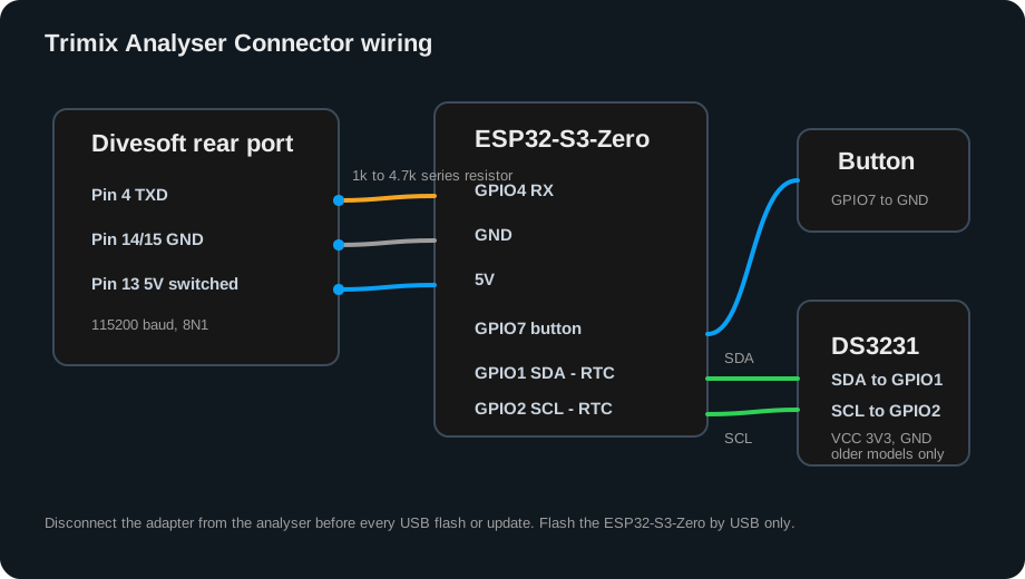
Follow the labelled clock connections in the diagram
Solder only the labelled connections shown in the diagram.
Prepare and dry-fit.Print the housing, fit the DVI connector and bare ESP32-S3-Zero-compatible board, and confirm the two M2.5 × 6 mm screws close the enclosure without touching the board.
Check enclosure and connector fit
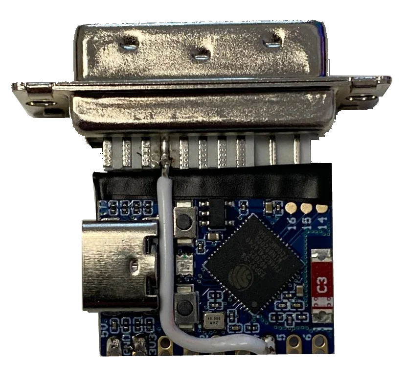
Solder the data wire.Connect Divesoft rear connector pin 4 directly to ESP32 GPIO4, exactly as shown in the diagram.
Top-side board and wire routing
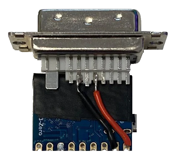
Connect ground and optional power.Connect Divesoft pin 14 or 15 to ESP32 GND. If powering from the analyser, first measure and confirm switched 5 V on pin 13 before connecting it to ESP32 5 V.
Bottom-side soldered connections
Add only the needed options.The analyser pause normally triggers printing, so the separate button is optional. Add the clock module only for an older analyser without a usable date.
Follow the diagram for optional partsOptional button and clock
Flash with analyser wiring removed.Disconnect the adapter completely from the analyser. Connect only USB to the ESP32 board, open the installer in desktop Chrome or Edge, and use full install for a new board.
USB only—no analyser connectionSafe browser flashing
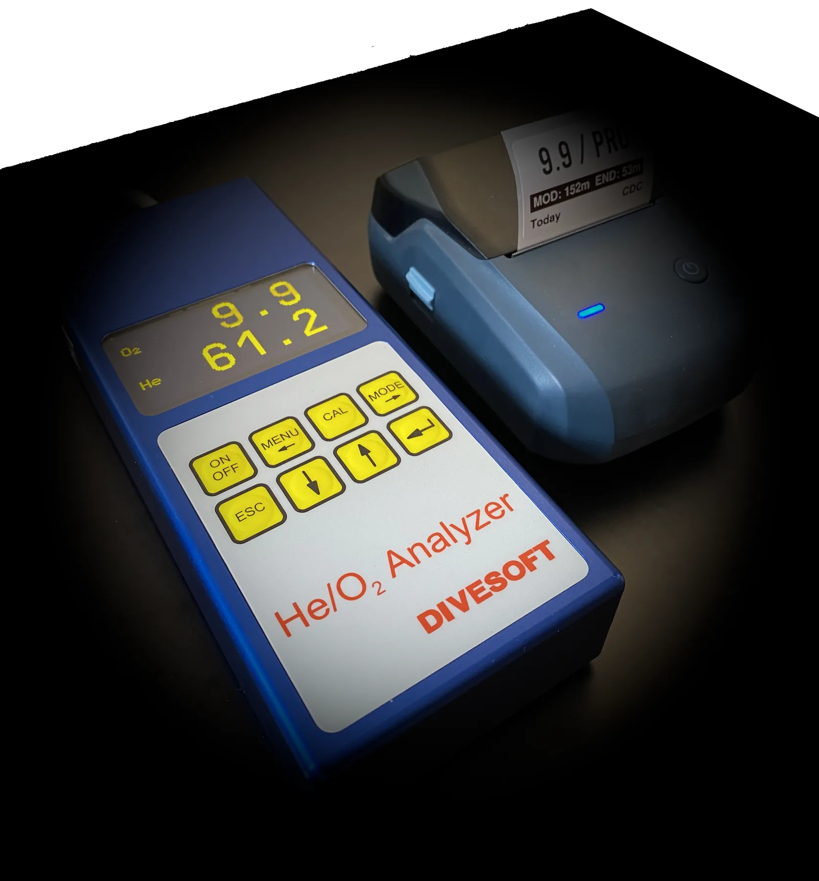
Enable Divesoft data output.On the analyser select Menu → Preferences → Send Data to USB → On; some firmware calls it Data output. Without this setting, the adapter cannot receive live values.
Enable output before checking live data
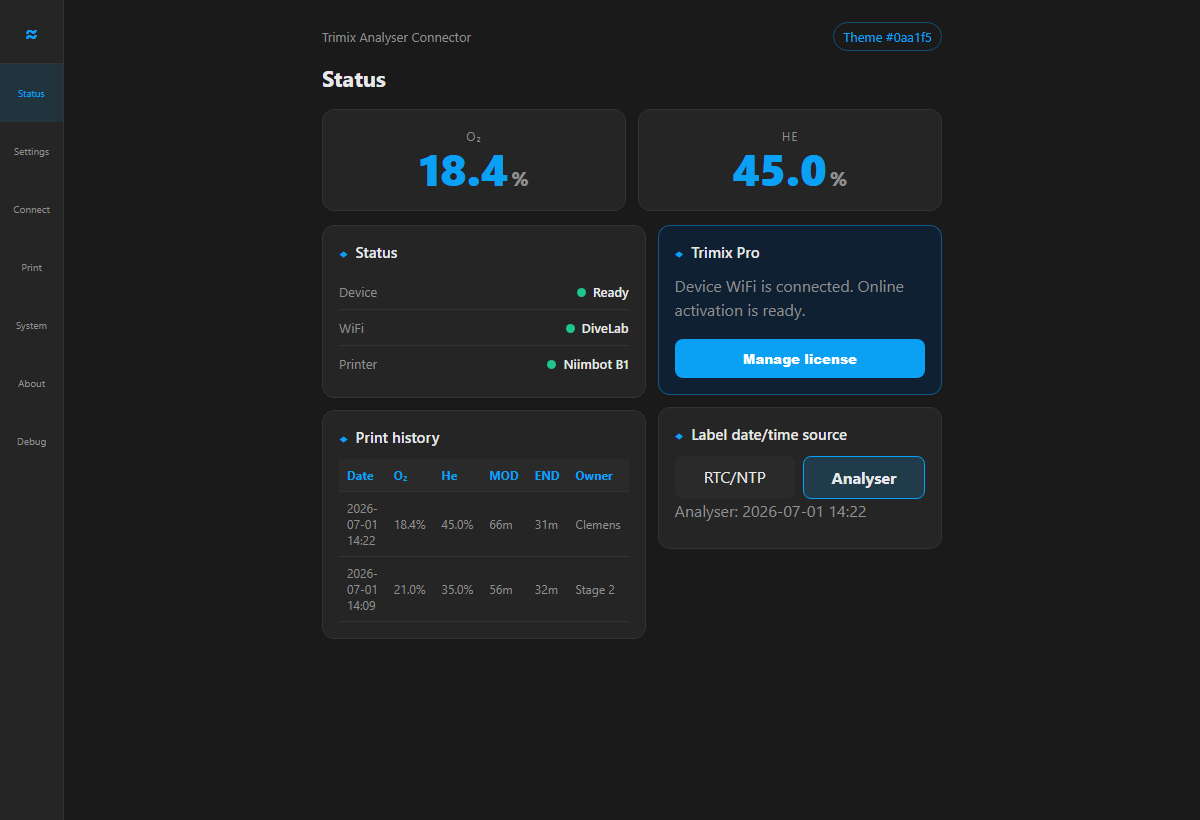
Configure the local Web UI.Join the setup Wi-Fi, add owner initials, pair the Niimbot printer, set the clock source and label options, and confirm basic or Pro licence status.
Printer, Wi-Fi, owners, and labels
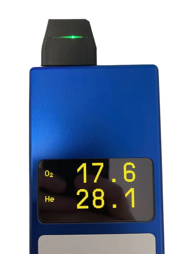
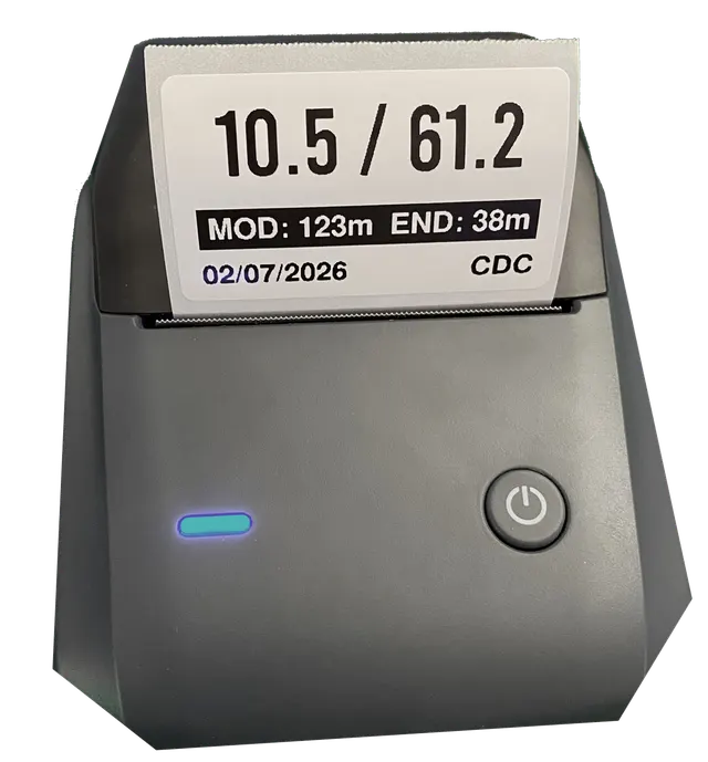
Verify readings and a label.Compare live O2 and He values with the Divesoft display, trigger one label, and verify mix, MOD, END, date, and initials before field use.