Simple builder guide
Connect the Divesoft analyser to the adapter
Switch on one analyser setting, solder the labelled wires shown in the diagram, flash the ESP32-S3 board, and compare the adapter readings with the analyser display.
Disconnect the adapter completely from the Divesoft analyser before connecting the ESP32-S3 board to USB.
Required setting
Enable Send Data to USB
On the Divesoft analyser open Menu → Preferences → Send Data to USB → On. Some firmware labels the setting Data output. The adapter can power up normally yet receive no O2 or helium values when this setting is off.
On the analyser
- Open Menu → Preferences.
- Set Send Data to USB to On.
- Some versions call the setting Data output.
- Check that the analyser itself shows valid O2 and helium values.
- Switch it off before connecting the adapter.
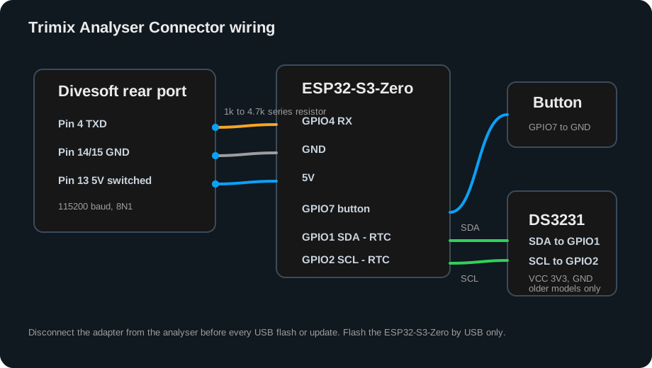
Three labelled connections
- Divesoft pin 4 to ESP32 GPIO4.
- Divesoft pin 14 or 15 to ESP32 GND.
- Optional: Divesoft pin 13 to ESP32 5V for analyser-powered use.
- Optional: push button between GPIO7 and GND.
- Leave every connection not shown in the diagram unconnected.
Finish the build
Solder, flash, plug in, and check
- Solder the wires.Follow the diagram for data, ground, and optional power. Check for loose strands or solder bridges.
- Flash the board.Leave the analyser disconnected. Connect only the ESP32-S3 board by USB and use the browser installer.
- Plug in the adapter.Remove USB, connect the completed adapter to the analyser, and switch the analyser on.
- Check the result.Confirm that O2 and helium on the adapter match the Divesoft display before pairing the printer.
Fault isolation
The adapter powers up but shows no readings
| Check | Expected result |
|---|---|
| Divesoft setting | Send Data to USB or Data output is enabled. |
| Analyser measurement | The Divesoft display itself shows valid O2 and He measurements rather than an error. |
| Ground wire | Divesoft pin 14 or 15 is soldered to ESP32 GND. |
| Data wire | Divesoft pin 4 is soldered to ESP32 GPIO4 with no loose wire or solder bridge. |
| Power | The board starts normally and was not left connected to USB while attached to the analyser. |